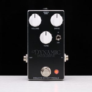
KRAUCYK EFFECT PEDALS
Handcrafted in the Northwoods
About Kraucyk Effect Pedals
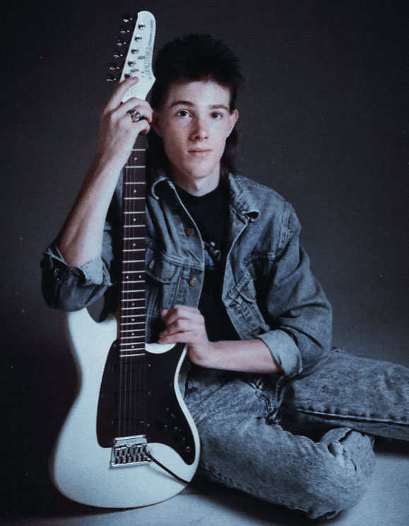
1986 Ibanez Roadstar II - RG135
Kraucyk Effect Pedals, or KEP, is the work of one person, me, Shannon Kraucyk. I became infatuated with guitar based music at an early age and my goal, through KEP, is to help other guitar players find their tone at an affordable price.
I bought my first guitar, a 1986 Ibanez Roadstar II, at age 16 (1989). For the next 20 years, I played many budget solid state amps and a single guitar pedal, a Soundtank TS-5 Tube Screamer. I was never really satisfied with my guitar tone (full disclosure, I’m primarily a bass player and was much more focused on my bass gear). In 2009, while searching for that Marshall tone, I built my first tube amp based on the Marshall 18 Watt 1974x circuit. That led to my interest in guitar pedals, and modifying budget pedals with the help of e-books sold by Brian Wampler.
I began learning more about guitar pedal circuits by reading books and articles written by Craig Anderton, Jack Orman, Douglas Self, R.G. Keen, Merlin Blencowe and many others. It has become my passion to not only recreate classic guitar pedal circuits, but to improve upon them.
My Process
Step One - Research
Once I find a circuit I’m interested in, I research the circuit. I locate, examine, and compare different schematics available through web searches. I study the circuit to determine how it works and how the designer used the circuit’s components to get the desired effects. I locate “gut shots” of the pedals and compare them to the available schematics to ensure they are accurate. I listen to various demos of the pedal and read reviews by other guitar players to determine whether the circuit is great as it is, or if there room for improvement. Can I add an additional control to make the pedal more useful? Can I change or add a component to make it better? Does the transistor’s gain / diode’s forward voltage make a difference in the circuit, and if so, how can I measure the component’s value to ensure it works as desired in the circuit? I sometimes breadboard the circuit, or build a rough prototype using perfboard, to experiment with the circuit.
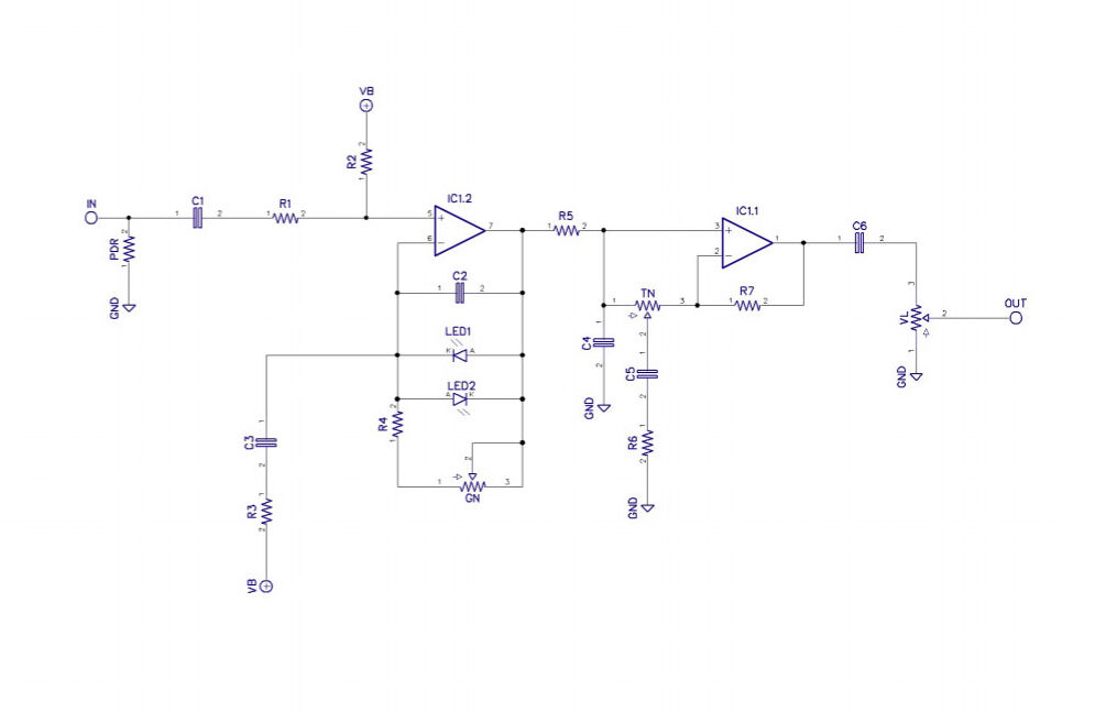
Step Two - Draw Schematic and Design Prototype Circuit Board
After researching the circuit, I draw a schematic that I am confident is accurate. While drawing the schematic, I incorporate any modifications I would like to further investigate.
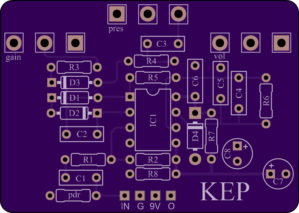
I then design a circuit board for my project. In designing circuit boards, I adhere to basic circuit board design guidelines, while also keeping in mind how the controls will be presented to the user. My primary focus is to design an efficient circuit board and keeping signal traces short. Although I do want an aesthetically pleasing circuit board, I am more concerned with it’s function.
Once I’m happy with my prototype circuit board, I send it to Osh Park for production.
Step Three - Prototyping
Once I receive my prototype boards from Osh Park, I build the circuit using sockets for all semi conductors, along with other components I flagged for experimentation during my research. I often build two prototype pedals so I can A / B test them against each other to determine which components I prefer. When prototyping, I pay attention to component placement to ensure my production circuit board is easy to build. I often make changes to the circuit board before I have them manufactured in bulk.
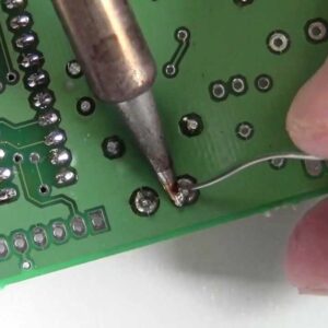
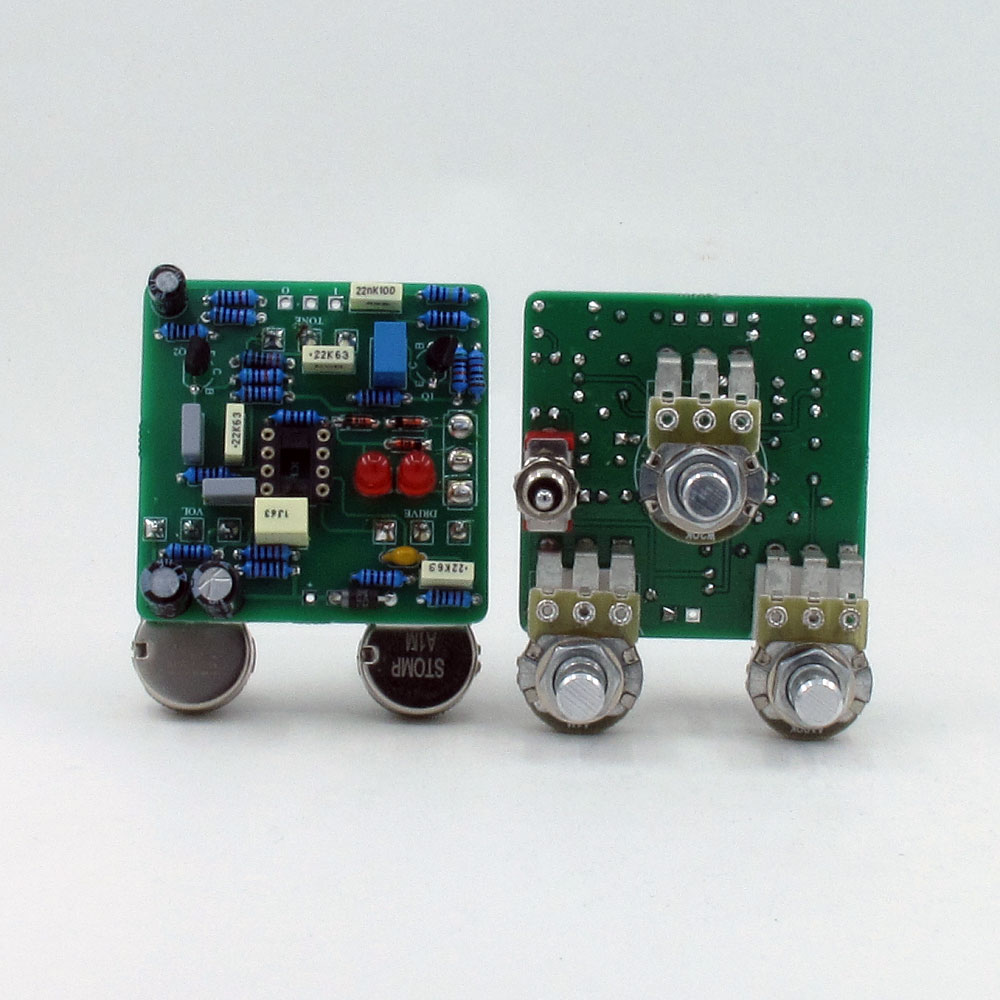
Step Four - Production - Populating Circuit Boards
After I receive my manufactured circuit boards, I hand solder all components and wires to the circuit board. I use low noise metal film resistors, and quality capacitors such as Nichicon, Epcos, Vishay, and Kemet. All components are tested prior to installation to ensure they are within spec.
Some components, such as transistors and diodes, need to meet certain benchmarks to work properly in some circuits. I use a Peak DCA75 Atlas Pro Advanced Semiconductor Analyzer to ensure these components are appropriate for the circuit.
All wires are reinforced with hot glue for additional durability.
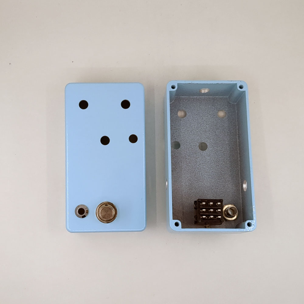
Step Five - Preparing the Enclosure
Once the circuit boards are populated and I test the circuit on my testing rig, I drill the pedal enclosures using a 3d printed template. I install a professional quality 3PDT stomp switch and an LED bezel. The pedal is now ready for final assembly.
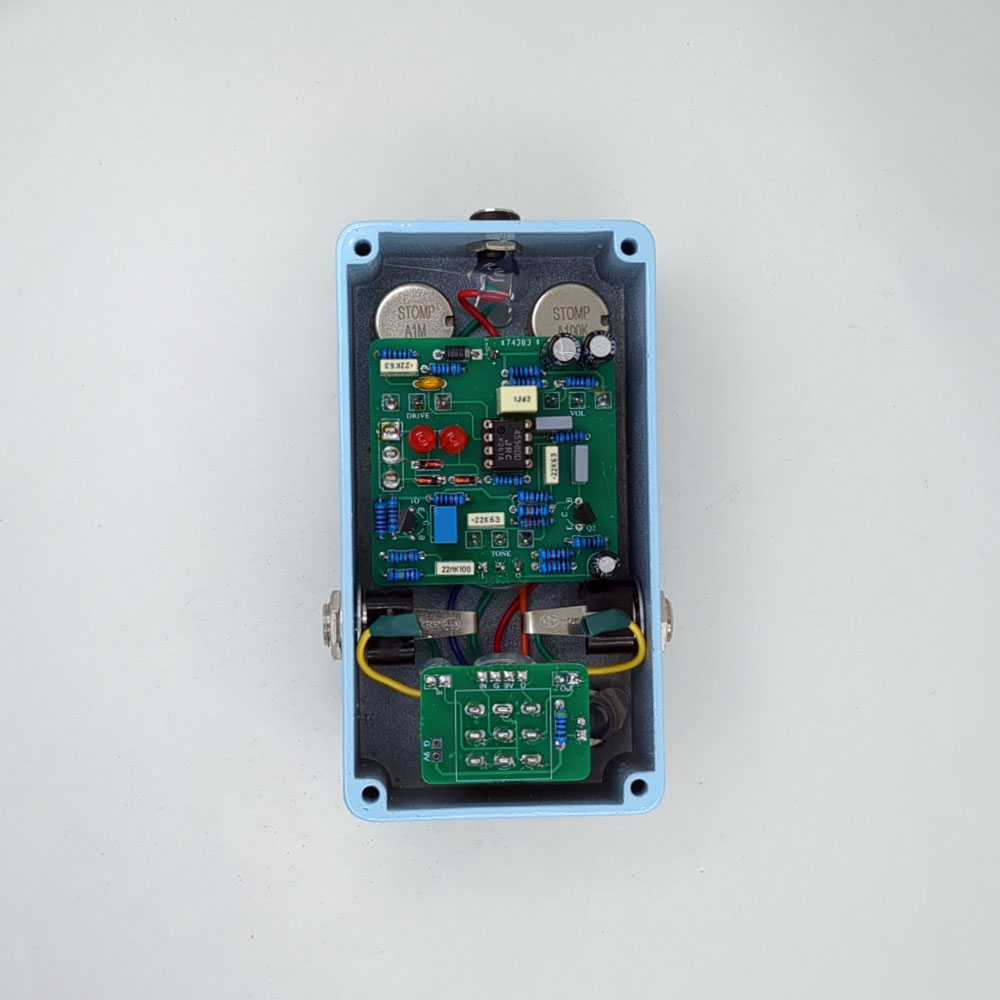
Step Six - Final Assembly
During final assembly, I secure the populated circuit board to the enclosure and hand wire it to my bypass board as well as the input, output, and power jacks.
All hand soldered wires are reinforced with hot glue or heat shrink for additional durability.
Step Seven - Testing
Once the pedal has been assembled, I play the pedal though my Ditto looper pedal for approximately four hours to ensure none of the components I used in the build are faulty.
After removing the pedal from the Ditto looper, I sign and date the back plate and attach it to the pedal. I install the knobs and play the pedal against my original prototype build. The pedal is then ready to ship.